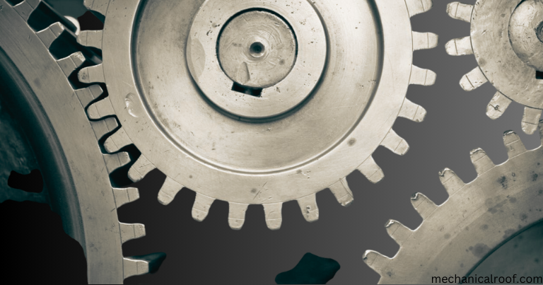
What IS A Gear?
A Gear rotating round device that has tooth in its structure that transmit torque and speed from one shaft to any other is referred to as a equipment.
Gears are also referred to as cogs, that have enamel cut into the gears or wheels. These enamel mesh together and transmit torque and pace. Gears are mechanical devices that paintings at the horizontal principle. The presence of gears permits the path, velocity and torque of the drive to be modified.
Gears are simple machines, however they come in one-of-a-kind sizes and might produce exceptional torques, as a consequence giving them a mechanical benefit. Their velocity relies upon on the rate of rotation and the diameter of the 2 interlocking systems attached to them. The tooth are the identical form and flippantly spaced on all gears. The enamel produce torque and save you tools slippage. When two or greater intermeshing gears work in collection, it’s far called a gear box or equipment teach. A linear gear p.C. Is called a rack, and translational motion occurs whilst the meshing movements in a linear direction.
Gears may be classified by way of form and axis vicinity. Gear shapes consist of involute, cycloid, and tricoid shapes. The axis location can be parallel axis gears or intersecting gears, and non-parallel axis gears or non-intersecting axis gears.
Usually, the toothed element is attached to the shaft of an object, which rotates when a driving force is carried out to it. The pushed tools additionally performs translational and rotational movement. Gears are described through their radius and quantity of enamel.
Types of Gears
The key to selecting gears is to have a clean knowledge of the one-of-a-kind kinds of gears to make sure proper power transmission in your system layout. One issue in deciding on gears is their dimensions, which includes module, number of tooth, attitude, and face width.
Gearboxes, also called equipment drives, are designed to boom the torque of the force motor, lessen the velocity produced through the motor, and exchange the course of rotation of the rotating shaft. The tool or motor is connected to the transmission via a grasp, belt, chain, or shaft. As you may think, gears are the heart of the transmission. They paintings in pairs and paintings together to transmit strength.
Gears are vital for the proper functioning of strategies, devices, machines and complicated mechanisms. They flow between various parts and transmit pressure, strength and torque easily and efficiently. Gears are categorised by way of type, class and the manner they maximize their effectiveness. Understanding the forms of gears and their parameters enables in successfully making plans the operation of equipment and mechanisms.
Bevel Gears
Bevel gears are conical in form and the tooth of this tools are arranged around the conical surface. These gears are used in programs that require a exchange of rotation around the axis. These gears switch electricity and power to intersecting shafts by changing the rotation. The constituent angle required for bevel gears is typically ninety tiers, but now not constantly. Bevel gears are made from cast metal, mild metal and alloy metal. Each has distinctive characteristics that allow for one-of-a-kind programs.
Crown Bevel Gears
Crown bevel gears, also called face gears or crown gears, have spiral helical tooth with a lead perspective of ninety°. They mesh with different bevel gears, spur gears, and pinion structures to exchange the rotational motion at a proper attitude. The teeth protrude at proper angles to the plane of the wheel, giving them the advent of a crown of enamel. Unlike tapered bevel gears, crown bevel gears are cylindrical and can be combined with different gears depending at the tooth design.
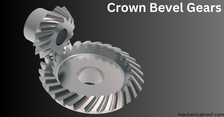
Crown gears are often used in programs where low noise is needed. When used with a rack locking block, it lets in the gear to rotate with the rack. Crown gears fell out of use inside the early twentieth century however have become more famous once more as industry moves in the direction of more energy efficient and technologically superior drives. The proper combination of crown gears, cars, gearboxes and manage structures can bring about enormous strength financial savings.
The use of crown gears is because of decentralization of force generation and is becoming increasingly crucial with elevated flexibility in business techniques and an increasing number of drives. There are high demands on green gears and a crown gear connection is needed.
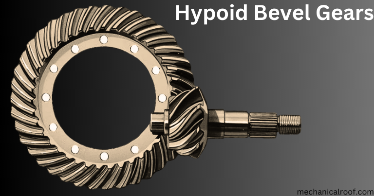
Hypoid Bevel Gears
Hypoid bevel gears can transmit rotational force among right-angle shafts and are usually utilized in heavy truck drivetrains. Hypoid gear units have a smaller tools shaft (pinion) offset from the larger gear shaft (crown tools) so they do now not move. The shaft offset permits the pinion diameter and helix perspective to be larger, enhancing contact place and teeth power.
The spiral perspective lets in the pinion equipment to mesh smoothly with the crown tools. The elevated enamel thickness and contact place allows for a wide gear ratio and the transmission of better torque. The advantages of this layout include much less wear, friction, strength loss, and higher efficiency.
n addition, hypoid gears can transmit loads to multiple enamel simultaneously, with a median number of tooth in touch starting from 2.2:1 to two.Nine:1. Hypoid gears can transmit better torque than further sized bevel gears due to teeth-to-tooth contact.
Hypoid gears offer many benefits and are getting more and more famous for reduction gears as the demand for energy transmission and movement manipulate structures increases. Manufacturers are growing motor flanges with hypoid gears to permit plenty of automobiles to be installed without delay into the gearbox housing.
Bevel gears are broadly used in the cement, beverage, meals, mining, electricity and bulk materials industries. Major programs for these gearboxes include medium to huge conveyors, shredders, water remedy, mixers, etc.
Miter Bevel Gears
Right angle gearboxes are used as proper angle drives with a 1:1 equipment ratio among intersecting shafts and are used in which excessive performance is needed. For bevel gears to mesh, each gears must have the equal variety of tooth, pitch and stress perspective, however or greater bevel gears may be used in a fixed.
The thrust of the bevel gears will separate the bevel gears, so ball or simple bearings need to be used to take in the back thrust. All bevel gears are mounted at proper angles, and hardened bevel gears provide 50% extra power and resist more put on than non-hardened bevel gears. The huge range of programs of proper perspective gears is their potential to deal with excessive speeds and excessive torque hundreds easily and quietly. Since attitude bevel gears have the equal variety of teeth, they can not boom or lower the transmission speed, so they can handiest be used to trade the transmission course. Angle bevel gears with spiral enamel are paired from proper to left.
Spiral Bevel Gears
Spiral bevel gears have curved enamel angles. They are more angled than immediately bevel gears, which creates a gentler contact between the enamel. This gentler tooth engagement appreciably reduces vibration and noise even at high speeds. Spiral bevel gears also are available with left and proper perspective teeth. Spiral bevel gears are tough to fabricate and feature a complex shape. However, it has more potent enamel, smoother operation, and less noise in the course of operation.

Straight Bevel Gears
Straight bevel gears are the most typically used in many industries because their teeth design is very simple and clean to manufacture. The tooth of heterosexual bevel gears are designed so that after flawlessly matched instantly bevel gears come into contact, they mesh immediately, now not step by step. This misalignment of teeth creates loud noise at some point of operation and additionally increases the weight at the tools enamel. All of this reduces the existence and durability of the gear and the machine.
Zerol Bevel Gears
Zerol gears are a combination of spiral gears and spur gears. These gears have all of the properties of both forms of gears. Zerol gears are gears with curved enamel organized directly on a tapered floor. This means that Zerol gears are used for the equal purposes as spur gears, but Zerol gears are a great deal quieter and feature less friction than spur gears. Additionally, Zerol gears aren’t set at an angle, which will rotate in any course and are available in both left and proper surpassed variations.
Internal Gears
An inner equipment is a equipment whose enamel are on the interior of a cylinder diameter. Internal gears transmit excessive power in tight spaces and are perfect for low noise, low vibration, low reduction and occasional fee. Internal gears are also known as sprockets and are perfect to be used wherein space is an difficulty. When external gears are coupled together they rotate in opposite guidelines and whilst outside and inner gears are coupled collectively they rotate inside the same path.
Internal gears are crafted from one of a kind substances depending on the software. Commonly used are cast metal, cast metallic, floor metal, aluminum and plastic.
Helical Gear
Helical gears are a kind of equipment with parallel arrangement. This kind of gear is also used for non-parallel and non-intersecting arrangements. The enamel of a helical gear revolve round a cylindrical body and are angled toward the tools face. Helical gears are designed with enamel angled left and right.
This angled enamel design gives helical gears the advantage of being able to connect with other gears in a one-of-a-kind way than instantly gears. When a mating pair is flawlessly matched, the contact between the corresponding tooth is maximized and spaced aside, instead of all of the enamel meshing immediately. This system reduces noise generated by means of the device and places less pressure on the tooth.
Parts of a Gear
Gears are used to transmit rotation from one shaft to every other and to alternate the output velocity of a shaft. They are often used for heavy hundreds because the enamel permit first-rate manage of the shaft movement.
Gear Head – The enamel of a gear project outward from the pitch circle for outside gears and inward for internal gears. This projection of the tools is the radial distance between the diameter of the component and the diameter of the equipment (called the gear head), and the recommendations of the gear form a gear head circle.
Shaft – The shaft controls the direction of the equipment movement and how that movement is finished. Parallel axes is the maximum not unusual axis configuration where the two axes are parallel. In intersecting axes, the axes are at proper angles to every different and are used to alternate the course of movement. While parallel and intersecting axes are the most common axis configurations, there are also non-parallel or non-intersecting gears.
Base Circle – A base circle is a theoretical construction used to create involute curves for developing enamel profiles.
Circular Pitch – Circular pitch is the distance from a fixed factor on one enamel to the identical fixed factor on an adjoining enamel, measured alongside the pitch circle. Due to the curvature of the gears, the measurements are arcs instead of strains. For the gears to mesh properly, the circumferential distance (additionally called the space between the teeth) of both gears must be the identical.
Tooth Depth – Tooth intensity is the intensity of the enamel between the pitch circle and the inner diameter or bore.
Diametric Pitch (DP) – Diametric pitch is the ratio of the range of teeth to the diameter of the element. Gears must have the equal diametric pitch for correct meshing. In the United States and UK, it is expressed in teeth per inch. As the quantity of tooth according to inch will increase, the enamel profile becomes smaller.
Fillet Profile – The fillet profile of a gear teeth, additionally called a trochoid, is a by-product of the tools slicing action and is placed just earlier than the cutter tip indentation at the tools teeth.
Profile Diameter – The profile diameter is an imaginary circle created by using connecting the trochoid or fillet curves of a gear tooth. It is referred to as the involute profile diameter (TIF) and is smaller than the diameter of the bottom circle.
Gear Ratio – Gear ratio indicates how generally a tools need to rotate to make one revolution of any other tools. It is an instantaneous degree of the speed ratio of or more meshing gears. If the driven equipment is larger than the driven gear, the latter will rotate quicker. Conversely, if the pushed equipment rotates smaller than the pushed tools, the previous will rotate quicker.
Pitch Circle – The pitch circle defines the scale of a gear that have to contact any other equipment to mesh. It is an imaginary circle that passes via every enamel of a gear and has a radius that lets in it to come back into touch with a similar circle.
Pressure Angle – The stress perspective is the attitude fashioned by the tangent to the pitch circle and the regular to the enamel profile at the pitch circle. It is decided through the tool used to shape the involute curve of the gear. Standard stress angles are 14.Five°, 20°, and 25°. The stress angle determines how the gears touch and how much pressure is shipped along the tooth. For gears to mesh, their pressure angles need to be the equal.
How Gears Work
Gears are mechanical devices which can be generally round and have tooth-like systems on the ends or tops. Gears are used in many machines to provide rotational force and torque for operation. Gears paintings in pairs, with the tooth of one tools meshing with the other to save you slippage.
If the gear pair is circular, the rotational speed and torque produced are steady. However, if it isn’t always circular, the rate and torque ratio can also change.
As the pair actions, the speed decreases and the torque of the gears increases. However, if the pinion had been at the driven shaft, the rate would boom and the torque could lower. The shafts on which a pair of gears are placed should be positioned close to every different, however at a distance from each other. The axes of rotation can be parallel, non-parallel, intersecting or non-intersecting. The gears are related to each other by way of an axis of rotation. This wave acts as a lever. The important feature of gears is to switch strength or rotation from one element to another. Multiple gears may be linked on the same time. Three things take place with gears:
Increase speed:
If two wheels are related and one has 40 enamel and the alternative has 20 teeth, the smaller wheel with 20 teeth will circulate two times as speedy because the first wheel to preserve up with the speed of the gears. It will keep up with the velocity of both motorcycles. The velocity will growth but the pressure required to move the smaller wheel will decrease.
Increase pressure:
If the smaller wheel has extra teeth than the larger wheel, it’s going to move slower and the force could be extra. This method that more force is wanted to move the smaller wheel.
Changing Direction:
When connected gears flow, one tools moves clockwise and the other movements counterclockwise. If you want to alternate the perspective of motion, you must use a special type of equipment committed to this function.
Applications of Gears
Gears are an crucial a part of enterprise, used to transmit movement and strength in clocks, instruments, machines, automobiles and industrial system. They are designed to sluggish down or growth the rate of motorized device and change the route of force easily and efficiently. Since their introduction lots of years in the past, gears had been an critical tool in industrial innovation and improvement.
Manufactured from durable substances, gears play a essential position in gadget productiveness and production operations. Each sort of equipment has specific elements, capabilities, advantages and characteristics that meet the requirements and specifications of operation and electricity transmission. With a huge variety and variety of gears to be had, there’s a gearbox to in shape every application.
Setting the speed
Power transmission
When transmitting electricity, the gears mesh with every different with out slipping, growing a tight bond. A gadget motor won’t be designed to transport a shaft immediately, but rather makes use of gears to transmit strength to the shaft to force the device.
Torque Variation
Torque is the rotational force produced through cars and machines and is regulated by means of using gears, equipment sets, gearboxes and equipment assemblies. Smaller gears produce less torque at the same time as larger gears produce greater torque. If a small gear is a using tools riding a larger gear, the torque will increase and the speed decreases. Conversely, making a bigger gear the riding equipment and a small gear the pushed gear reduces the torque and increases the speed.
Direction of Force
A common use of gears is to change the path of rotation or movement, which is finished by way of unique design of the tools pair. The course of rotation of a motor is determined through the rotation of the shaft, however the tools configuration can also exchange the course of rotation.
Gears
Gears are one of the maximum common programs of gears and encompass selected gear sorts in a housing. Gears consist of computer virus, bevel, helical, and spur gears designed to exchange torque, velocity, strength, movement, and force. Transmissions are a essential component of engine-powered motors and gasoline-powered machines.
Conclusion
- A gear is a circular device with enamel on its circumference that is used to generate rotational movement and torque.
- Gears are typically round, however different shapes consisting of square may be to be had.
- The velocity and rotation relies upon on the size of the tools and its mate.
- The axes of gears may be parallel, non-parallel, intersecting or non-intersecting.
- A variety of substances are used to fabricate gears, together with metals, stainless steel, plastics, copper alloys and nickel alloys.
- Every cloth has sure homes and can be chosen depending at the utility.
- Wood and resin are also used to fabricate gears.
- There are many one of a kind varieties of gears, every with specific properties.
- These are differentiated primarily based on their configuration and application.
- Spur gears, helical gears, double helical gears, rack gears, internal gears, bevel gears, malicious program gears and planetary gears are distinctive forms of gears.
- Some work on parallel axes while others work on non-parallel axes.
- Plastic gears are now normally used in many industries due to their low price and smooth availability.
- Gears are used in lots of industries such as vehicles, water pumps, toys, family appliances, trains, scales and trendy shipment dealing with.


