
What Is A Bevel Gear?
Bevel gears are toothed rotating device factors used to transmit mechanical strength or shaft power perpendicularly or diagonally among intersecting shafts. This adjustments the axis of rotation of the shaft power. In addition to this feature, bevel gears can also boom or decrease torque and affect angular velocity in opposite directions.
A bevel equipment may be imagined as a truncated cone. On its side, it has milled tooth that mesh with different gears with their very own tooth. The gear that transmits the strength of the shaft is known as the riding tools, and the gear to which the power is transmitted is known as the pushed tools.
Usually, the range of enamel of the using gear and the pushed gear are distinct to provide a mechanical advantage. The ratio of the quantity of tooth of the pushed gear to that of the driving equipment is called the gear ratio, and the mechanical advantage is the ratio of the output torque to the input torque. This dating is expressed by way of the following equation:
MA=TbTa=rbra=NbNa 𝑀𝐴=𝑇𝑏𝑇𝑎=𝑟𝑏𝑟𝑎=𝑁𝑏𝑁𝑎
MA is the mechanical advantage, τb and τa are the torque, rb and ra are the radii, and Nb and Na are the range of teeth of the driven and driving gears, respectively. From this equation, we will see that increasing the variety of enamel of the pushed equipment will increase the output torque.
On the other hand, as the mechanical energy will increase, the output velocity of the pushed equipment decreases. This is expressed through the subsequent equation:
MA=WaWb 𝑀𝐴=𝑊𝑎𝑊𝑏
ωè and ωb are the angular velocities of the driving and driven gears respectively. Generally, a gear ratio of 10:1 is usually recommended for bevel gearboxes. To growth the velocity of the driven equipment, a tools ratio of 1:five is suggested.
Bevel gears are typically paired and should not be used interchangeably. Bevel gears are assembled in a special manner due to their inherent transmission of thrust and radial loads. Unlike spur gears, which typically transmit handiest radial hundreds, they may be assembled in a special way. All bevel gears are perfectly positioned for surest performance.
Types Of Bevel Gears
There are many exclusive varieties of bevel gears, labeled with the aid of tooth profile and orientation. More complicated kinds consisting of spiral bevel gears and hypoid bevel gears are the end result of advances in production strategies including CNC machining.
1-Straight Bevel Gears
Straight bevel gears are the handiest shape of bevel tools. When prolonged, the teeth shape a instantly line that intersects at the wheel axis. The enamel are tapered so that the outer or heel a part of the tooth is extra than the internal element or tip. Bevel gears specifically have an instantaneous touch line, which means larger tolerances throughout meeting. The disadvantages whilst the usage of this type are vibration and noise. This limits instantly bevel gears to low pace, static load applications. A commonplace application for straight bevel gears is in automotive differential systems.

Straight bevel gears are the perfect to manufacture. The earliest production technique for producing straight bevel gears is the use of a planer with a dividing head. With the creation of the Revacycle and Coniflex structures utilized by Gleason Works, greater green manufacturing strategies have been developed.
2-Spiral Bevel Gears
Spiral bevel gears are the main complex design of bevel gear. The tooth of a spiral gear are curved and inclined, rather than the enamel orientation of a immediately bevel tools. This permits for greater overlap between the teeth, promoting slow meshing and disengagement because the teeth touch. Spiral bevel gears have higher load distribution and better load sporting potential because of the numerous tooth in touch. This allows for compactness in comparison to instantly bevel gears of the equal ability.
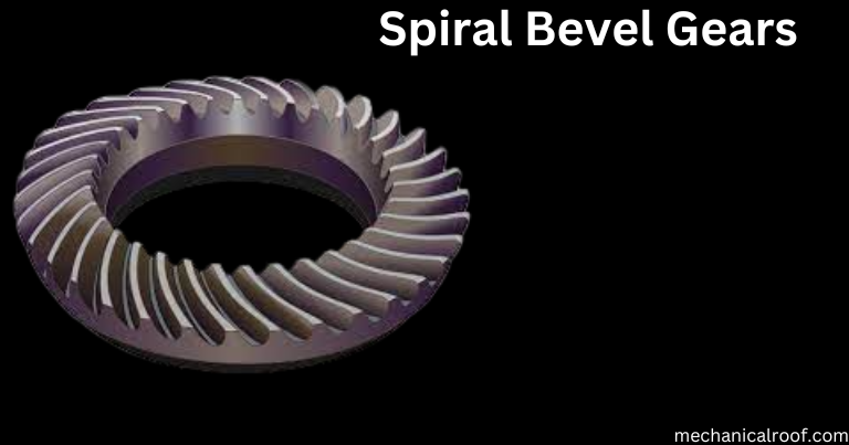
The downside of spiral bevel gears is that they convey large axial masses, which require more luxurious bearings. Spiral bevel equipment assemblies commonly require thrust bearings with rolling elements. Furthermore, spiral bevel gears are synthetic in matching sets; exceptional tools units of the same design are not interchangeable until deliberately designed that way. Spiral bevel tools units are manufactured in right or left hand. The tooth of
spiral bevel gears are usually shaped via a equipment gadget, which we can talk in greater detail later. This manner guarantees high precision and floor excellent. Lapping is also executed to complete the enamel and gain the desired enamel position.
3-Zerol Bevel Gears
This type is a change of the Gleason Works trademarked immediately bevel tools. Zero bevel gears have enamel curved longitudinally. These gears also are comparable in profile to spiral bevel gears. The distinction lies inside the helix perspective: 0 bevel gears have a helix attitude of zero°, spiral bevel gears have a helix attitude of 35°.

Like directly bevel gears, zero bevel gears do no longer generate excessive axial masses. Therefore, undeniable bearings can be used. The Zerol type can be replaced with the aid of a straight bevel equipment with out changing the housing or bearings. Additionally, the tooth of a Zerol bevel equipment have a slight overlap effect because of their curvature, similar to spiral gears.
The enamel of a Zerol bevel gear are created by using a rotary milling cutter. The curvature of this cutter creates a longitudinal curvature in the teeth. Zerol bevel gears are made to high precision and are often machined by using lapping or grinding.
5-Hypoid Bevel Gears
Hypoid bevel gears are a unique type of bevel tools wherein the shaft axes are neither intersecting nor parallel. The distance between the two equipment axes is called the offset. The tooth of hypoid bevel gears are helical, similar to spiral bevel gears. A hypoid bevel tools with out offset is actually a spiral bevel tools. Manufacturing and forming hypoid kinds is much like manufacturing and forming spiral bevel gears.
Offset permits the helix perspective of the smaller equipment (pinion) in a hypoid bevel tools set to be large than the helix diameter of the larger tools. The ratio of the variety of teeth of the gears is not directly proportional to the ratio of the gears’ pitch diameters or theoretical operating diameters. This permits a bigger pinion to be fitted to a given size of pushed gear, enhancing the pinion’s energy and presenting a higher mesh ratio with the larger equipment. In return, hypoid gears can transmit extra torque and function at higher equipment ratios.
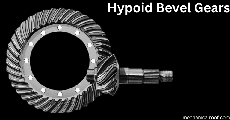
Additionally, with sufficient offset, bearings can be located on both facet of the gears for the reason that shafts do no longer move. However, they’ve the drawback that efficiency decreases as the displacement will increase.
Hypoid wheels are quieter and produce minimum vibration as compared to spiral wheels. However, while the use of hypoid gears, apart from the performance issues referred to above, there is a downside that the tooth flanks generally tend to slip greater. This means that unique lubricants need to be used.
6-Miter Bevel Gears
A sort of bevel equipment with a equipment ratio of one:1, because of this that the using and pushed aspects have the equal variety of tooth. Angle gears provide no mechanical gain, so this type of functionality is constrained to changing axis or rotation. Usually, the axes of bevel gears intersect perpendicularly. In a few assemblies, the shafts can be orientated to intersect at any angle. These are known as bevel gears. Bevel gears have shaft angles among 45° and a hundred and twenty°. The reduce of the tooth on miter bevel gears can be directly, spiral or zero-angled.

Manufacturing Processes Of Bevel Gears
There are four important tactics for manufacturing gears: steel cutting, casting, molding and powder metallurgy. Metal slicing is the maximum broadly used procedure due to its excessive dimensional accuracy. The ultimate , casting and molding, are utilized in special instances, as an instance the manufacturing of big gears by casting. Casting is toward the final form and therefore reduces machining prices.
Another form of molding, injection molding, is used to manufacture plastic gears. On the other hand, forming may be completed through bloodless drawing or forging. In cold drawing, a clean is drawn or extruded thru a sequence of dies to shape the tools shape. During forging, the blank is pressed in opposition to a parent fabric with the desired enamel shape. Due to work hardening from continued deformation, the resulting gear is more difficult and has a extra contoured grain.
Gear machining can be similarly divided into 4 classifications, summarized underneath:
- Rotating thread gear: hobbing, producing grinding
- Rotating and reciprocating tools: forming, scraping, generating grinding
- Rotating disc wheels: milling, forming grinding, thread grinding
- Linear gear: broaching, punching
Not all strategies are relevant to bevel gears due their conical design effects in a tapered intensity and width. For reducing bevel gears, steel reducing strategies can be converted into categories: face milling and face milling.
End hobbing: End hobbing is a continuous indexing procedure for generating gears. A collection of cutting blades progressively cut via all the enamel until the desired depth is reached. As one institution of blades cuts a enamel, the following group of blades enters the space among the next teeth. The slicing tool and workpiece rotate simultaneously.
Face milling: Face milling is a unmarried indexing technique in which the cutter wheel or tool is fed in to cut the enamel hole and indexes to the next teeth area. The cutting device and workpiece are reduce in sync. Each teeth is milled till all teeth have reached the specified intensity. Face milling can be finished the usage of a two-tool planer, dual rotary cutter, single row milling cutter, or a 5-axis CNC milling system.
Powder Metallurgy: Powder metallurgy is the procedure of producing merchandise or substances from metal powders. In its only shape, this is performed by means of grinding the preferred fabric into a powder, compressing the powder in a mould, and then sintering it. This manufacturing procedure is valued because secondary finishing often does not require steel removal tactics, resulting in less waste and lower prices. Gears made through this manner are evidently porous, making them lighter and quieter.
Bevel Gear Applications
Using bevel gears is one of the simplest and most green approaches to change the axis of rotation in a drivetrain. The type of bevel equipment, and the producing and completing methods used, vary depending on the kind of software. Below are some applications of bevel gear systems:
Bevel Gears in Automotive The maximum not unusual use of bevel gears is in automobile differentials.
The differential is the a part of the front or rear axle that lets in the wheels to show at special speeds. This allows the car to nook while keeping managing and traction. The driveshaft is connected to a hypoid tools inclusive of a pinion and a hoop tools. The ring tools is hooked up on a carrier in conjunction with different bevel gears in a planetary gear set.
Bevel Gears in Heavy Machinery: Bevel gears are utilized in heavy machinery either for propulsion (which include the differential systems in automobiles) or as auxiliary components.
Bevel Gears in Aviation: Bevel gears are used within the aviation industry in electricity transmission structures for helicopters and in gear drives for aircraft add-ons.
Bevel Gears in Industrial Plants: An example of an business plant that uses bevel gears is a cooling tower fan. The motor is normally set up on the deck of the cooling tower with its shaft axis horizontal. The gear assembly reduces the velocity and increases the torque whilst realigning the axis of rotation vertically.
Bevel Gears in Marine Gearboxes: Bevel gears are frequently utilized in marine gearboxes as a part of the stern power. Two pairs of bevel gears are used among the engine and the propeller.
Bevel Gears in Hand Tools:
- Drills – Bevel gears are maximum normally utilized in drills. As the drill cope with rotates vertically, the bevel equipment inside the drill chuck changes direction to horizontal, and the bevel gear controls the velocity of rotation to allow for drilling into a variety of substances.
- Planers – Planers are used to provide a form to a workpiece via linear movement. The use of bevel gears in planing allows for adjustments during the planing technique and for displacements caused by deflection.
Conclusion
- Bevel gears are rotating device elements used to transmit mechanical power perpendicularly or diagonally between two intersecting shafts. In addition to changing the axis of rotation, bevel gears also can produce mechanical advantage with the aid of growing the output torque.
- However, producing mechanical advantage reduces the angular pace of the pushed shaft. Hence, bevel gears can also be used as discount mechanisms.
- Efficiency is the ratio of output electricity to input electricity. Power losses in bevel gears are in particular because of friction due to sliding contact. This is then launched as warmness, that is normally dissipated through lubricants.
- Bevel gears have an performance of ninety seven-ninety nine.Five%, except hypoid bevel gears, that have an performance of 90-98%. As the offset of the hypoid wheel increases, the performance decreases even greater.
- There are many terms to describe gears. The maximum essential for bevel gears are pitch diameter, stress perspective, shaft attitude and quantity of tooth. These are the important thing values that decide the tools geometry.
- There are 3 foremost techniques of producing gears: slicing, casting and molding. Of those three methods, shearing is the most commonly used. Powder metallurgy is also used.
- Gear machining is similarly divided into several strategies. One is the usage of rotary thread cutting tools which include hobs. The second is the usage of rotary or reciprocating reducing tools that mate with the equipment clean. Thirdly, the cut is completed the use of a rotating disc wheel, as is commonplace in milling. Finally, the equipment reducing is performed the usage of a immediately forming or broaching device.
- The most not unusual utility of bevel gears is in automobile differentials. They are discovered in cars as well as light and heavy machinery. Other predominant packages encompass the aviation and maritime industries.


